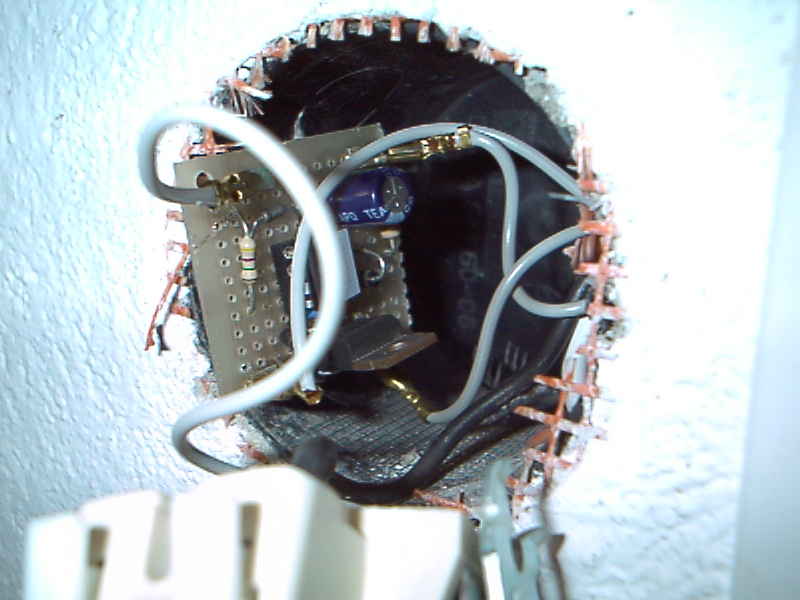
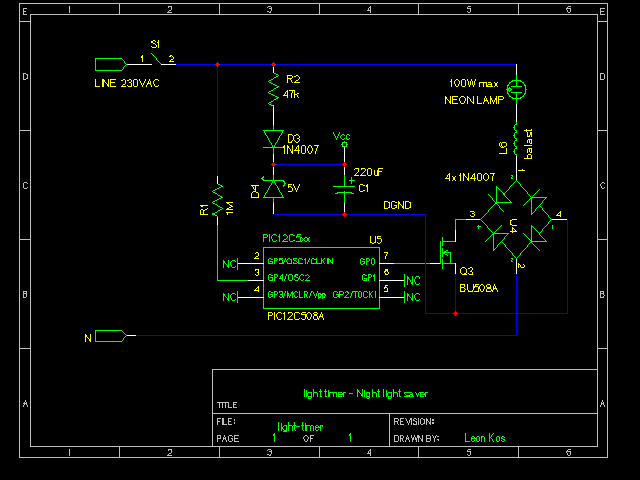
Bridge can be used instead of four 1N4007 diodes. Note thad PIC processor uses DGND for GND. Supply resistor can be R1 can be changed up to 150k. Power NMOS transistor can be of any type which can whidstand current and voltage of the load. Mains resistor can be up to 4M7. See larger photo.
Postscript schematics, PDF or gschem,
;**********************************************************************

;                                                                     *

;    Filename:	    light-timer-nosleep.asm                           *

;    Date:          16.5.03                                           *

;    File Version:  0.2.0                                             *

;                                                                     *

;    Author:        Leon Kos                                          *

;    Company:       LECAD - University of Ljubljana                   *

;                                                                     *

;                                                                     *

;**********************************************************************

;                                                                     *

;    Notes:                                                           *

;                                                                     *

;                                                                     *

;**********************************************************************


	TITLE 'Light timer'

#define C508
#ifdef C508
	list p=12c508a
	#include <p12c508a.inc>
	__CONFIG _CP_OFF & _WDT_ON & _MCLRE_OFF & _IntRC_OSC
freemem		EQU	0x07
#define		MAINS	GPIO, 4
#define		LAMP	GPIO, 0
#define		IOPORT	GPIO
#define		OUT_SET 0x10
#else
	list      p=16F84             ; list directive to define processor

	#include <p16F84.inc>         ; processor specific variable definitions

	__CONFIG   _CP_OFF & _WDT_ON & _PWRTE_ON & _XT_OSC
freemem		EQU	0x0F
#define		MAINS	PORTB, 2
#define		LAMP	PORTB, 6
#define		OUT_SET  0x04
#define		IOPORT	PORTB
#endif


	RADIX	DEC

;***** VARIABLE DEFINITIONS


temp		EQU	freemem	;zacansni reg

state		EQU	freemem + 1 ; operating state for flags

pulse		EQU	freemem + 2 ; pulse delay

cnt		EQU	freemem + 3 ; delay counter

day		EQU	freemem + 4 ; counter

#define		SINUS	state, 0	; edge detector status


		ORG     0x1FF             ; processor reset vector

; Internal RC calibration value is placed at location 0x1FF by Microchip

; as a movlw k, where the k is a literal value.


;**********************************************************************

		ORG     0x000             ; processor reset vector

#ifdef	C508
		movwf   OSCCAL            ; update register with factory cal value

;		goto	main		; we can program two times

;		ORG	0x80		; if the code size < 128bytes

#endif

main
		clrf	day		; clear day counter

		clrf	day+1
		clrf	day+2
		bcf	LAMP
		movlw	OUT_SET
		tris	IOPORT
		movlw	0xF8
		option

		movlw	20		; count several periods

		movwf	cnt
		clrwdt
stable_zero	btfss	MAINS
		goto	stable_zero	; to stabilise line

		clrwdt
stable_one	btfsc	MAINS		; to debounce when

		goto	stable_one - 1	; when plugging in

		decfsz	cnt, F		; mains

		goto	stable_zero

		bsf	LAMP	; switch on the LAMP


mainloop	btfss	MAINS
		goto	mains_zero
mains_one	btfsc	SINUS
		goto	mainloop
		bsf	SINUS	; raising edge

		clrwdt

incday		incfsz	day, F		; increment day counter

		goto	day_check
		incfsz	day+1, F
		goto	day_check
		incf	day+2, F

day_check	movf	day, W		; check for round a day

		btfss	STATUS, Z	; if not goto

		goto	hour_check	; hour check

		movf	day+1, W
		xorlw	0xEB		; 0x41EB00 sine waves

		btfss	STATUS, Z
		goto	hour_check
		movf	day+2, W
		xorlw	0x41
		btfss	STATUS, Z
		goto	hour_check
		bsf	LAMP		; lamp ON

		clrf	day		; day overlap

		clrf	day+1
		clrf	day+2
		goto	mainloop

hour_check	movf	day, W		; one hour is 0x2bf20 waves

		xorlw	60h
		btfss	STATUS, Z
		goto	mainloop
		movf	day+1, W
		xorlw	0x3d
		btfss	STATUS, Z
		goto	mainloop
		movf	day+2, W
		xorlw	0x08
		btfss	STATUS, Z
		goto	mainloop
		bcf	LAMP		; lamp OFF

		goto	mainloop


mains_zero	btfss	SINUS
		goto	mainloop
		clrwdt
		bcf	SINUS
		goto	mainloop

		END                     ; directive 'end of program'
 ;**********************************************************************

; *
 ; Filename:
light-timer-wdt.asm *
 ; Date: 16.5.03
*
 ; File Version: 0.2.0 *

; *
 ; Author:
Leon Kos *
 ; Company: LECAD -
University of Ljubljana *
 ; *

; *
 ;**********************************************************************

; *
 ; Notes: not
working *
 ; *
 ; *
 ;**********************************************************************


  TITLE 'Light timer'

 ;#define C508
 #ifdef C508

list p=12c508
	#include <p12c508a.inc>
	__CONFIG _CP_OFF & _WDT_OFF & _MCLRE_ON & _IntRC_OSC
freemem		EQU	0x07
#define		LAMP	GPIO, 0
#define		IOPORT	GPIO
#define		OUT_SET 0x08
#else
	list      p=16F84             ; list directive to define processor

	#include <p16F84.inc>         ; processor specific variable definitions

	__CONFIG   _CP_OFF & _WDT_ON & _PWRTE_ON & _XT_OSC
freemem		EQU	0x0F
#define		LAMP	PORTB, 6
#define		OUT_SET  0x08
#define		IOPORT	PORTB
#endif


	RADIX	DEC

;***** VARIABLE DEFINITIONS


temp		EQU	freemem		;temporary  reg

day		EQU	freemem + 1 	;sine wave counter

hour		EQU	freemem	+ 4	;time light is on


;**********************************************************************

		ORG     0x000             ; processor reset vector

#ifdef	C508
		movwf   OSCCAL            ; update register with factory cal value

#endif

main		movlw	OUT_SET
		tris	IOPORT

		btfsc	STATUS, NOT_TO	; watchdog timeout?

		goto	sleep_test
		btfss	LAMP
		sleep
		bcf 	LAMP		; WD timeout.

		movf	day, W		; Set switch off time

		movwf	hour
		movf	day+1, W
		movwf	hour+1
		movf	day+2, W
		movwf	hour+2
		sleep


sleep_test	btfss	STATUS, NOT_PD
		goto	mainloop	; wake up from sleep?

		bsf	LAMP
		clrf	day		; clear day counter

		clrf	day+1
		clrf	day+2
		movlw	20h		; two hours is 0x2bf20 waves

		movwf	hour
		movlw	05h
		movwf	hour+1
		movlw	00h
		movwf	hour+2
		clrwdt

mainloop

incday		incfsz	day, F		; increment day counter

		goto	day_check
		incfsz	day+1, F
		goto	day_check
		incf	day+2, F

day_check	movf	day, W		; check for 0x41EB00 sine waves

		btfss	STATUS, Z	; if not goto

		goto	hour_check	; hour check

		movf	day+1, W
		xorlw	0Bh		; EB

		btfss	STATUS, Z
		goto	hour_check
;		movf	day+2, W

;		xorlw	41h

;		goto	hour_check

		bsf	LAMP		; lamp ON

		clrf	day		; day overlap

		clrf	day+1
		clrf	day+2
		sleep

hour_check	movf	day, W		; two hours is 0x2bf20 waves

		xorwf	hour, W
		btfss	STATUS, Z
		sleep
		movf	day+1, W
		xorwf	hour+1,W
		btfss	STATUS, Z
		sleep
		movf	day+2, W
		xorwf	hour+2, W
		btfss	STATUS, Z
		sleep
		bcf	LAMP		; lamp OFF

		sleep


		END                     ; directive 'end of program'
Last modified: Thu Nov 27 13:27:25 CET 2003